

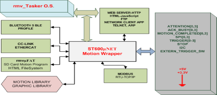
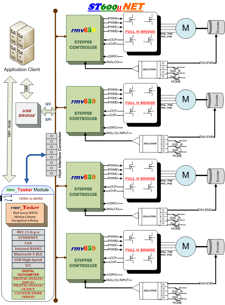
ST600µNet controls "four" stepper motors independently trough a set of triggers mode. Can be connected directly to a host computer via USB HDI link, or in conjunction with rmv_Tasker Module , allowing in this way a full IoT capabilities via Ethernet, or WI-FI. The ST600µNet Series can operate in both monophasic and biphasic mode, with step mode size as follows: full step, half step, quarter step, 1/8 step, 1/16 step, 1/32 step, 1/64 step, 1/128 step, and 1/256 step. The ST600µNet Series motor current depending on the model can drive: A) From 0.5 Amp to 4.5 Amps, and B) From 1 Amp to 8 Amp per axis. Furthermore, this series provides the capability of having a step rate as fast as 22,000 steps/second. Each Motor Manufacturer Parameters can be saved to RMV859 Internal Flash. In Addition, ST600µNet support the following Motion Mode: Trapezoidal, Speed Control, Profile Motion, S-Curve, PI, Current Controlled, Sequential Motion, Closed LOOP, and Voltage Constant. As part our commitment to "Open Source" ST600µNet application software will be supported to: Raspberry PI, Beaglebone, Arduino boards. Free samples can be downloaded via GitHub. Please see the link bellows.
| Step Modes | Full-Half step monophasic & biphasic, Micro Steps { ¼, 1/8, 1/16, 1/32, 1/64, 1/128, and 1/256 of step }. Mixed step size can changed in real time from extended speed commands. |
|---|---|
| Motor Current | Independent axis chopper driver setting from: A) 0.5 Amp to 4.5 Amp ,or B) 1 Amp to 8 Amp, depending of the model. Feedback winding current is measured during cycle by period. Chopper driver with over current protection, Over temperature protection, and Under Voltage Protection. Temperature heat sink can be read en real time allowing the best motor power consumption chopper temperature |
| Host Interface | HID USB Interface, full compatibility with: Linux, MAC OS, and Windows O.S, NO driver is needed. |
| Motion Mode | Speed control, Position Control, Trapezoidal, Velocity-contouring profile, Hardware Sequential Motion Setting, Electronics-Gear Profile, Parabolic, Spline, S-curve point to point profile. |
| Step Counter Register | −(231) to 231 − 1.Similar for Encoder Register when is enabled |
| Speed Register | Maximum slew rate ± 22,000 step/sec. |
| Motor Limits | Isolated limit switches left, right, home, and stop. Voltage supported from 5V to 24V. |
| FIFO Memory | Programmable Internal FIFO RAM 700 words for different steps mode. |
| Analog Channels | 2 analog input channels |
| Close Loop | PID loop algorithm, Motor bias, Output Limit, Encoder A, B, and Index (5V to 24 V input signal) for each axis. Ramp Controller, Speed calculation feedback. |
| Motor Parameters | In each axis, motor parameters can be programmed, like : motor inductance, winding current, winding resistanse, step per revolution, and motor power. This parameters will optimize motion performce for the application. |
| Trigger | Two Hardware Triggers: Isolated External (5V to 24V ), Internal Trigger. Software Trigger: Trigger and Sequential Trigger. |
| Emergency Stop | Isolated push button input for emergency stop. Range: (5V to 24V ) |
| Status Event Register | Motion Complete , Position wraparound, Trigger, Command Error, Limit Switch Reached, Home, FIFO Status, etc. |
| Activity Status Register | At maximum velocity , Position Tracking, Current Profile mode, Axis settled, Motor Mode, Position Capture, Step Mode, In-motion, S-curve segment, FIFO bytes free ,Program Counter, Command Counter, etc. |
| Internal Report Status | Encoder Counter Register, At HOME, At A Limit Switch, STOP, User digital IO's, Analog inputs, Chopper status, Steps Counter Register, FIFO Pointer, etc.. |
| Power Requirements | Signle Power supply range:16VDC-50VDC, regulated |
|---|---|
| Analog Channels | Two analog inputs: 4mA-20mA and (0V-5V) |
| Isolated Digital Inputs | Four input channels 5V to 24V |
| Isolated Digital Output | Six output channels 5V to 24V |
| Isolated Motor Signal | Voltage range: 5V-24V, Limit Switch: LSW_LEFT, LSW_RIGHT, HOME, STOP, EXTL_TRIGGER . |
| Isolated Encoder Input | Isolated Encoder inputs A, B and Index , Voltage Range: 5V-24V |
| Host Interface | USB 2.00 high speed HID, mini USB connector |
| Heat sink Real Time Temperature | Ready Temperature measurement for motor power calculations, Maximum =150 ºC |
| Digital Voltage Output | Voltage Output:5VDC, Maximum Current: 0.5 Amp |
| Two LED Indicators | "Orange": USB Connection ESTABLISHED, "GREEN": Healthy POWER ON |
| Board Dimensions | Dimensions: 8"x5", RoHs Comparable. |
| Operating Temperature | Industial Grade: -30ºC to +85ºC. High Temperature support, Conform to UL-CSA Standards. |
ST600µNet-4.5 (Motor Current
5 Amp continuous)
![]()
ST600µNet-8.0 (Motor Current 8.0 Amp continuous)
![]()
The latest application source code, user guide, ST600uNET.dll and
different library and O.S. support information, can be found at GitHub repository,
Please click the following link:
![]()